Search This Blog

Showing posts with label autocad basics. Show all posts

Saturday, 26 November 2011

3D A-CAD COMMAND "SLICE"


SLICE:

Slice command is used to cut the 3d objects based on fields imaged cutter. You can use the slice command by selecting one of the options that exist.

AutoCAD Slice Command

Command: slice
Select objects: 1 found
Select objects: Specify first point on slicing plane by 
[Object/Zaxis/View/XY/YZ/ZX/3points] <3points>:
Specify second point on plane:
Specify third point on plane:
Specify a point on desired side of the plane or [keep Both sides]: b

To use the slice command can be done in the following:
Type Slice in the command line
Select object to slice: Select the object to be cut
Specify the start point of slicing plane or [planar object/Surface/Zaxis/View/XY/YZ/ZX/3points] (3points): specify 3 points on the object to be done cutting
Specify a point on desired side or [keep both sides] (both): Determine the 3D Solid Objects that will be maintained. To select both objects still exist, type B

3D A-CAD COMMAND "EXPLODE"


EXPLODE:

Explode command is the reverse of the order pedit. AutoCAD commands to solve an object which originally consisted of one entity into an object that consists of many entities.

AutoCAD Explode Command

Usually explode command is often used to change the shape of the object polyline into line, making it easy to edit. Here's how to use the explode command:

Command: explode
Select Objects: (select the object to be explode) 
Select objects: enter

Type Exp or explode in the command line, and press enter. Next you are prompted to selectobjects to be parsed. And press enter to end the command explode

3D A-CAD COMMAND "BOUNDARY"


BOUNDARY:

Boundary command is used to create a form of duplication of objects in the form of a closed polyline or region based on a certain pattern.

AutoCAD Boundary Command

Form patterns result from duplication of the boundary command is very varied, depending on the object of the intersection between the two forms of composition that you create.

Boundary is also very useful to create a certain shape that is created from the intersection or the field of 2D slices.

AutoCAD Boundary Creations

If you would create the same object shape based on an existing form object, then you do not need to specify the size and form of depiction. This will add time and manufacturing process that is not necessarily easy.

Command: BOUNDARY
Pick internal point: Selecting everything...
Selecting everything visible...
Analyzing the selected data...
Analyzing internal islands...
Pick internal point: *Cancel*

Boundary methods for drawing
 commands application you can do in the following ways:
- Make sure you have made the composition of a closed area that will be used to make duplicates.
- Select the Draw menu - Boundary
- In the Boundary Creation dialog box, click Pick Points.
- Next select the object to be duplicated. To find out the results, removal of objects by using the Move command.

3D A-CAD COMMAND "SUBTRACT"


SUBTRACT:

Subtract command is used to reduce the region objects to 3D solid modeling objects. Subtract command is usually used for punching holes in an object such as a window or form a circle that has a hole in the middle like a donut.

AutoCAD Subtract Command

Command: su
Subtract Select solids and regions to Subtract from ...
Select objects: 1 found
Select objects: Select solids and regions to Subtract...
Select objects: 1 found
Select objects:

To use the Subtract command can be done by:
- Type su in the command line or in the menu bar Modify - Solid Editing - Subtract. Press Enter
- Next select the object to be reduced, press enter.
- Then select the object cutting, Enter.

3D A-CAD COMMAND "REGION"


Region command serves to establish the extents of a closed wake. A wake is said closed if its initial point to meet with the endpoint. Remember, the Region is not the surface. Therefore, face modification orders cannot be applied to objects that are orders Region.

AutoCAD Region Command
REGION :

Region over the indicator, where you can obtain the physical parameters (such as gravity, area andperimeter) of the object.

Command: region
Select objects: Specify opposite corner: 4 found
Select objects:
1 loop extracted.
1 Region created.

To run your region command can perform the following steps:
- At the command line type in the region or select an icon on the toolbar region draw
- Later select a closed object that will be the object region, and then press enter.

3D A-CAD COMMAND "PREDIT"


PREDIT :

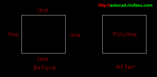
Pedit command is used to unify the entity-entity of multiple objects into one unified entity. The purpose of Pedit is to reduce the size of computer files from the image.

AutoCAD Pedit Command

This command is very important to understand very well to make it easier in the manufacture of 3D objects because the 3D object consists of the unity of the various forms of 2D objects.

Command: pedit
Select polyline or [Multiple]:
Object selected is not a polyline
do you want to turn it into one? 
Enter an option [Close/Join/Width/Edit vertex/Fit/Spline/Decurve/Ltype
gen/Undo]: J
Select objects: Specify opposite corner: 2 found
Select objects:
1 segments added to polyline
Enter an option [Close/Join/Width/Edit vertex/Fit/Spline/Decurve/Ltype
gen/Undo]:

Of the options listed by the prompt, only some are usefully employed through the Pedit Command. These are listed below and then discussed in greater detail on the following pages. Other options, especially Edit Vertex, are beter done through direct editng. In some cases, you might even prefer to use the Properties palette to edit Polylines.

- Close or Open: The Close and Open options add and remove the closing segment only direct editing removes any segment
- Join: Join command is easier to use
- Width: The Widty option applies to the entire polyline, the properties palette applies variable widths to segments.
- Edit Vertiex: The edit vertex option is painful to use
- Fit, Spline and Decurve: Converts polyline segments to area, to splines and curved segments to lines
- Ltype gen: Ensures linetypes are continuous through vertices
- Reverse and Undo: Reverse command is easier to use and the undo opton applies to the last actions inside the Pedit command, Undo command applies to everthing

3D A-CAD COMMAND "REVOLVE"


REVOLVE :

Revolve command used to create a 3D object by rotating a 2D object on the axis of rotation.

Command: rev / Revolve
Current wire frame density: ISOLINES = 4
Select objects: Specify Opposite corner:
Select objects: (Enter)
Specify the start point for axis of revolution or
define axis by [Object / X (axis) / Y (axis)]:
Specify endpoint of axis:
Specify angle of revolution (360):

AutoCAD Revolve Command

Command: Rev / Revolve
Rev. Type in the command line to activate the Revolve command

Select objects: Specify Opposite corner:
Select the object you want to play, and make sure the object in the form of polyline. If the object is still in the form of Line or objects that do not become one entity, then the object will not be at Revolve.

Specify the start point for axis of revolution or
define axis by [Object / X (axis) / Y (axis)]: 
Determine the point that is used to rotate the object.

Specify angle of revolution (360): 
Determine the desired rotation, maximum up to 360 rounds.

3D A-CAD COMMAND "EXTRUDE"


EXTRUDE:

Extrude is a Command to make a 3D object by giving the thickness of the 2D objects that are closed and form a single entity object.

AutoCAD Extrude Command

Command: ext EXTRUDE
Current wire frame density: ISOLINES=4
Select objects: 1 found
Select objects: (Enter)
Specify height of extrusion or [Path]: 23
Specify angle of taper for extrusion (0):

By using the Path, you can create a 3D objects from 2D objects in accordance with the form Path.

AutoCAD Extrude Command

Command: ext EXTRUDE
Current wire frame density: ISOLINES=4
Select objects: 1 found
Select objects: (Enter)
Specify height of extrusion or [Path]: p Select extrusion path or [Taper angle]:

A-CAD COMMAND "VIEWRES"


VIEWRES:

Viewres command (View Resolution) associated with the number of lines drawn in circles or arcs. Viewres regulated by varuabel, the higher the value of a given variable produces an image circle and the arc more smoother. However, it is also about the speed of appearance of the use of the zoom and pan commands.

AutoCAD Viewres Command

The general form viewres command as follows:
Command: viewres
do you want to fast zomm? [Yes / No] (Y):

At the first prompt, AutoCAD provides the question of speed to use the Zoom. At this prompt, if you answered Yes, after the zoom, the appearance of circles and arcs are less smooth, except at second prompt is selected high resolution, so as to produce smooth a circular shape and a arc.
Enter circle zoom percent (1-20000) (100): (Provide a high resolution value and press enter)

A-CAD COMMAND "TRIM"


TRIM:

Trim command is used to cut a portion of the object like line, arc, circle, xline, rays, polyline and spline with find another object as a line cutter

AutoCAD Trim Command

Command: trim
Current settings: Projection = UCS, Edge = None
Select cutting edges ...
Select objects or (select all): 1 found
Select objects:
Select object to trim or shift-select to extend or [Fence / Crossing / Project / Edge / Erase / Undo]:

There are several options on the command trim that you can use, among others, as follows:

MEANING = Select object to trim or shift-select to extend or [Fence / Crossing / Project / Edge / Erase / Undo]:

- Fence Option is used to select the object image by using the fenceline, each object will be selected when exposed to the trajectory fence line. Fence line can be irregularly shaped trajectory, but it is a straight line.

- Option Crossing the same as fence lines, crossing option is used to select the affected image object trajectories crossing the line and / or inside the lines crossing. In contrast to the fence, crossing the line in the form of rectangles.

- Project Option is used to working on 3D images. With this option you can cut objects that are not in one area. At the same Project option there are three sub-options, None, UCS and View.

None will make the trim option ignores objects located in different areas so that the cut only the objects in the same field.

UCS option will create an object based on a plan to cut trim UCS now and ignore the object is in the same plane or not.

View options using the fields seem to determine the line of sight cutting objects located in different areas.

- Option Edge will help you to cut objects that are not met by using a piece of pseudo-lines.

At the edge there are two sub-options option, which extend Extend and No, which is toggled or turns into default.

- Option you can use Undo to undo the last step you create the event of an error in workmanship. This command will create an object that has been cut back to its original form before being cut.

- Erase Option is used to remove objects that are not required when you run the command trim.

- Option to Extend Shift-select command used to change the trim to the extend command, you can do by pressing the Shift key and select the object intended.

Extend command will extend the object image. Once you release the Shift key, then the command returns a command trim.

NOTE :Type Trim and enter twice, after it click on object want to cut.